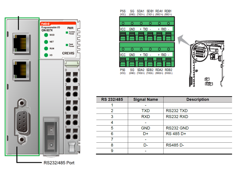
The GN-9372 Programmable IO Adapter from Crevis includes a 9-pin serial communication port with pins for both RS232 and RS485. The port can be used to control up to 20 Modbus RTU devices with RS485. The A800 VFD can be configured to operate with Modbus RTU commands by changing as few as four parameters. In this configuration the following were changed.
- Pr. 331 = 1 : set the RS-485 communication station number to 1
- Pr. 332 = 384 : set the RS-485 communication speed to 38,400 bps
- Pr. 340 = 10 : set the drive to start up in NET communication mode
- Pr. 549 = 1 : set the drive to operate with Modbus RTU protocol
Wiring diagrams: The Crevis PIO module uses 2-wire RS-485 communication
- Pin 6 D+ is connected to TXD1+ and RXD1+ on the A800 terminal block
- Pin 8 D- is connected to TXD1- and RXD1- on the A800 terminal block
The Crevis PIO adapters use the CODESYS programming environment. To activate the COM port for Modbus communication, a device must first be inserted into your project configuration tree. This port should be configured with the following settings.
- COM port = 2 (COM port = 1 would specify the RS232 communication.)
- Baud rate = 38400
- Parity = EVEN
- Data bits = 8
- Stop bits = 1
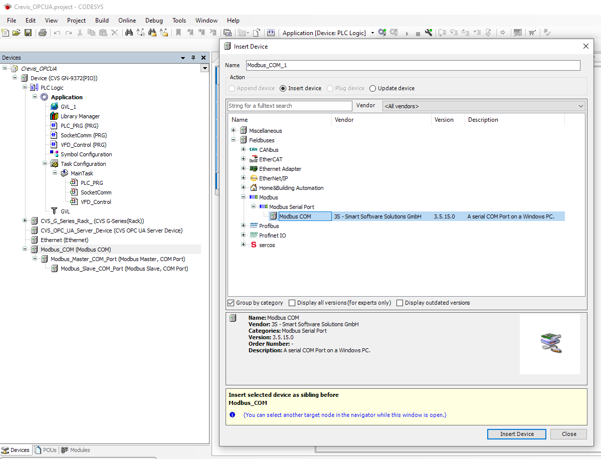
The port is defined to a be Master by appending the ‘Modbus_Master_COM_Port’ device to the ‘Modbus_COM’ device. Then the ‘Modbus_Slave_COM_Port’ is appended to the Master.
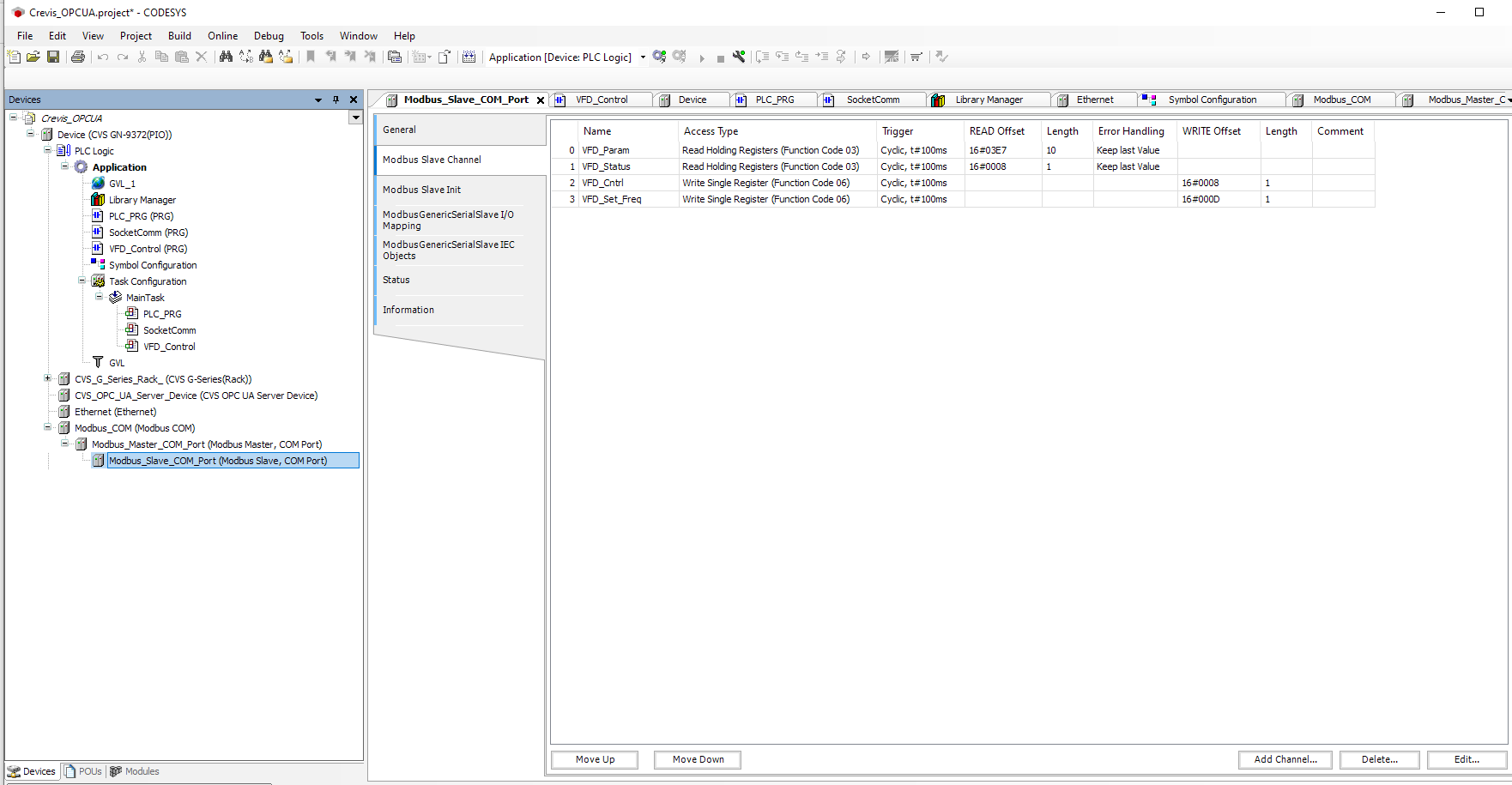
The detail page for this ‘Modbus_Slave_COM_Port’ is where the details of the VFD signals are defined. Channels are added to define the Modbus Function Codes and the Modbus Address that are to be accessed in the VFD. In the example shown, a group of 10 parameters are read, the VFD status word is read, the VFD control word is written, and a frequency setting is written.
The Modbus addresses for these items and others can be found in the A800 VFD instruction manual.
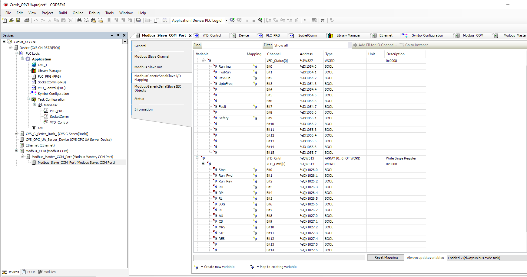
The final step is assigning variable names for the data being accessed. This is done via ‘ModbusGenericSerialSlave I/O Mapping’ .
In the example shown, variable names have been assigned to the individual bits of the VFD_Control word, and the VFD_Status word.
These defined variables are then available to be used as needed in the programming logic.
